
LightShearwalls (LSW), is meant for modeling and analyzing light-framed (primarily wood) structures with shearwalls. It features the ability to create a full-building model that combines gravity and lateral loading in a way that is compatible with Code rules for load-deflection relationships of wood shearwalls, which imply various sources of nonlinearity including: nail slip, hold-down slip, and different behavior at the boundaries in tension than in compression. LSW allows the designer to build a full 3D model of the structure, analyze it for gravity and/or lateral loading, review results including diaphragm and wall deflections and force demands, and verify that drift and capacity limits are met.
LSW feature the ability assign and run load combinations of Dead, Live, Roof Live, Earthquake or Wind, Rain and Snow loading. The designer can envelope results from load combinations to obtain a summary of how the analysis results. Gravity loading is assigned to individual elements typically as a tributary width or area and load per unit area.
The designer draws elements in a 2D CAD interface that represent various physical objects. The types of elements that can be modeled are:
- Diaphragms:
- Are rigid elements that constrain the lateral movement of the other elements that are connected to them.
- They are defined by drawing a 2D shape in plan. The location of lateral loading will be applied at the centroid of the shape.
- They are assigned a lateral load by the user (i.e. ELF procedure).
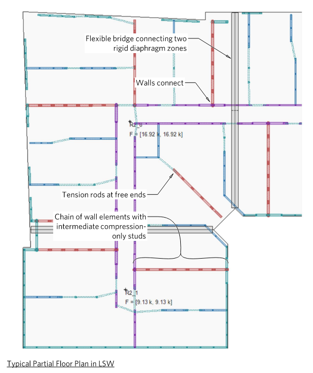
- Shearwalls:
- Connect one diaphragm (below) to another (above) with regard to lateral behavior.
- They are assigned a Shearwall Type, which controls the shearing behavior, i.e. force-deformation relationship in shear.
- They have a Boundary assignment at each end representing compression and tension behavior and control the force-deformation relationship for bending and axial actions.
- The boundaries are forced through the model validation process to stack on another boundary below (either another shearwall boundary or a transfer post), land on a beam, or be assigned as a supported vertically with a spring stiffness.
- The boundaries may be assigned different types at each end of the wall.
- They can have self-weight assigned through the Shearwall Type.
- They can have other gravity loading assigned by specifying a tributary width and unit area load.
- The boundaries may be assigned tributary area for gravity loading.
- Transfer Posts:
- With regard to lateral behavior, they do not contribute.
- They behave exactly like isolated, independent shearwall boundaries.
- Beams:
- May be used to model gravity-bearing beam members, collectors, or coupling beams.
- They can have gravity loading assigned by specifying a tributary width and unit area load.
- They must be supported by two or more shearwall boundaries, transfer posts, or other beams.
- Bridges:
- Connect two diaphragms with flexible element.
- They are assigned a Shearwall Type and Boundary Type that control shear, bending, and axial behaviors.
Analysis
Once the designer has defined the model and assigned all components, it validated for analysis. The validation ensures that all elements have valid types assigned to them. During the validation phase, the various elements are "connected" internally based on their locations. For example, a shearwall is assigned its upper and lower diaphragm, and a boundary checks to make sure it lands on a boundary or beam below. Also, two or more boundaries located in the same place are merged internally; the model isn't valid if two such boundaries have different types. The program reports validation errors that must be resolved for the analysis can be performed.
The analysis is a nonlinear iterative procedure using the Newton Raphson method. The wall element and overall iterative procedure is described on the following pages.
Once the analyses are complete, the designer may review for acceptability:
- Element forces and deformation responses (envelope or by load case)
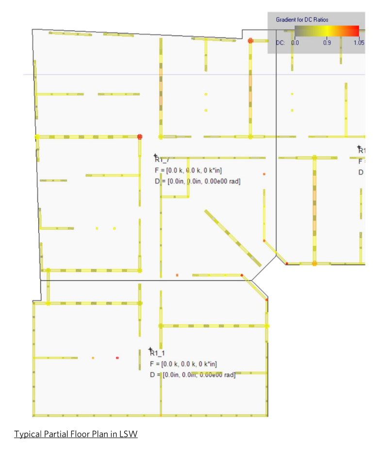
- Element demand/capacity ratios and
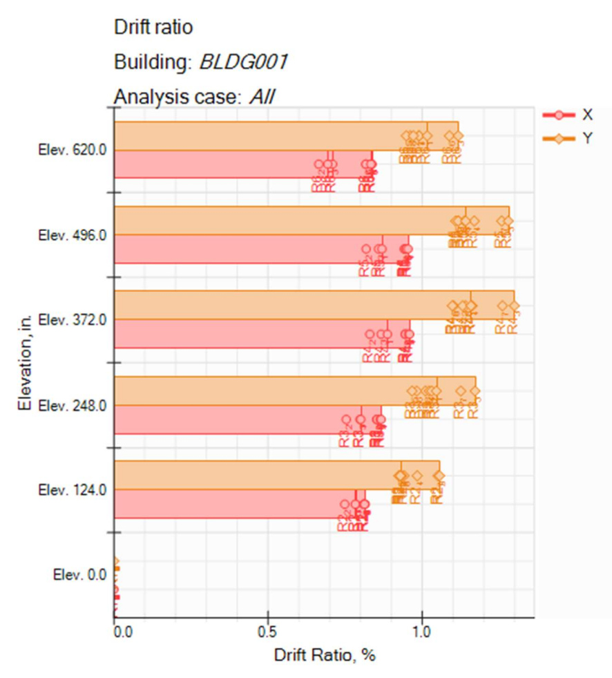
- Drift Ratios
The designer may also run OS analyses (nonlinear pushover) to get boundary forces for design of concrete podium slab. These are limited by either:
- Ω0 times design lateral load,
- 1.5 times the nominal strength of the boundary elements, or
- State of equilibrium where the lateral displacement is Cd times the displacement under design lateral load
Always free for students
Free, full-featured 30-day trial for everyone else
$1,500* per seat, per year (floating network license)
System requirements: Windows® 10 or 11, 8gb. RAM, 2gb. disk space,
.NET 4.7.2 or later, internet access to activate the software
Current Version: 2024.10.16.00 Download
- The price listed above is for a single seat for 1 year.
- Please contact us to inquire about multi-user and/or multi-year licenses: info@tippingapplications.com
- Prices are subject to change at any time.
- A 3% processing fee will be added to invoices paid by credit card.